
LASER DaSH-IT · STEP BY STEP
Plan a Frame and Read the Cut List
Turn a panel layout into a measured frame plan with a mockup, join details and stock estimates.
Screens captured from the current v1.8 development software. Feature names and availability may differ in the latest public installer. Screenshots illustrate software operation; they are not photographs of finished physical work. Updated October 14, 2026.
STEP 01 / 06
Finish the panel dimensions first
Complete the layout and per-piece size questions in Multi-Panel Studio. Frame dimensions depend on the assembled panel footprint, including gaps. A later change to panel count or spacing changes the frame plan too.
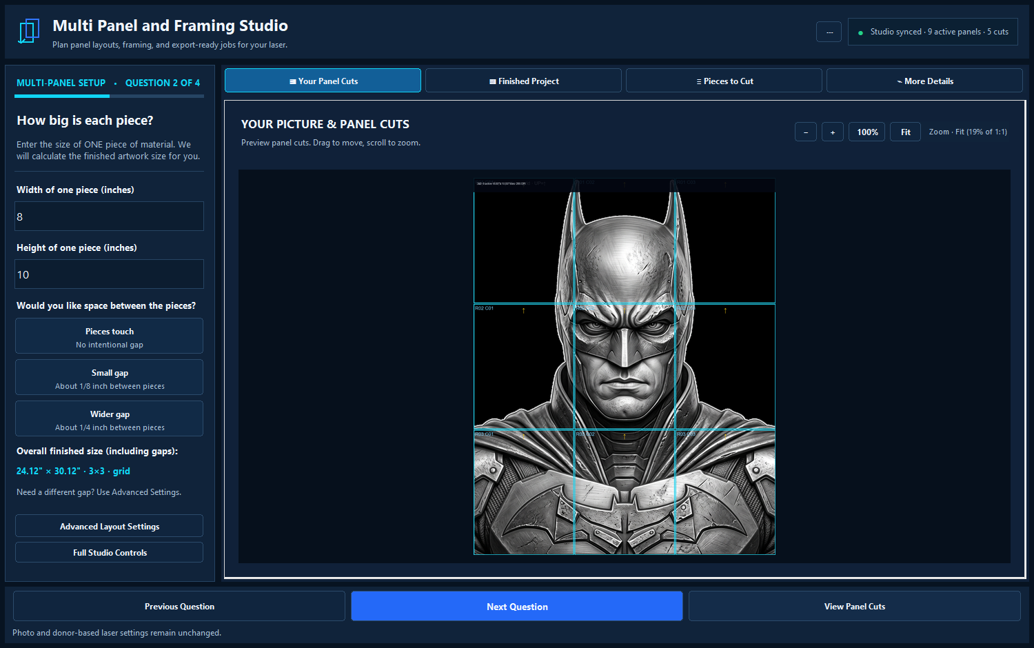
Checkpoint: The assembled size represents the actual pieces you will mount.
STEP 02 / 06
Choose a frame style and inspect the mockup
At the display question choose Gallery, Floating, Shadowbox, Slim or Heavy Duty. Click See Finished Project. Read the presentation brief beside the render: outside size, opening, frame style and supports. The render is an assembly visualization, not a photograph of a built frame.
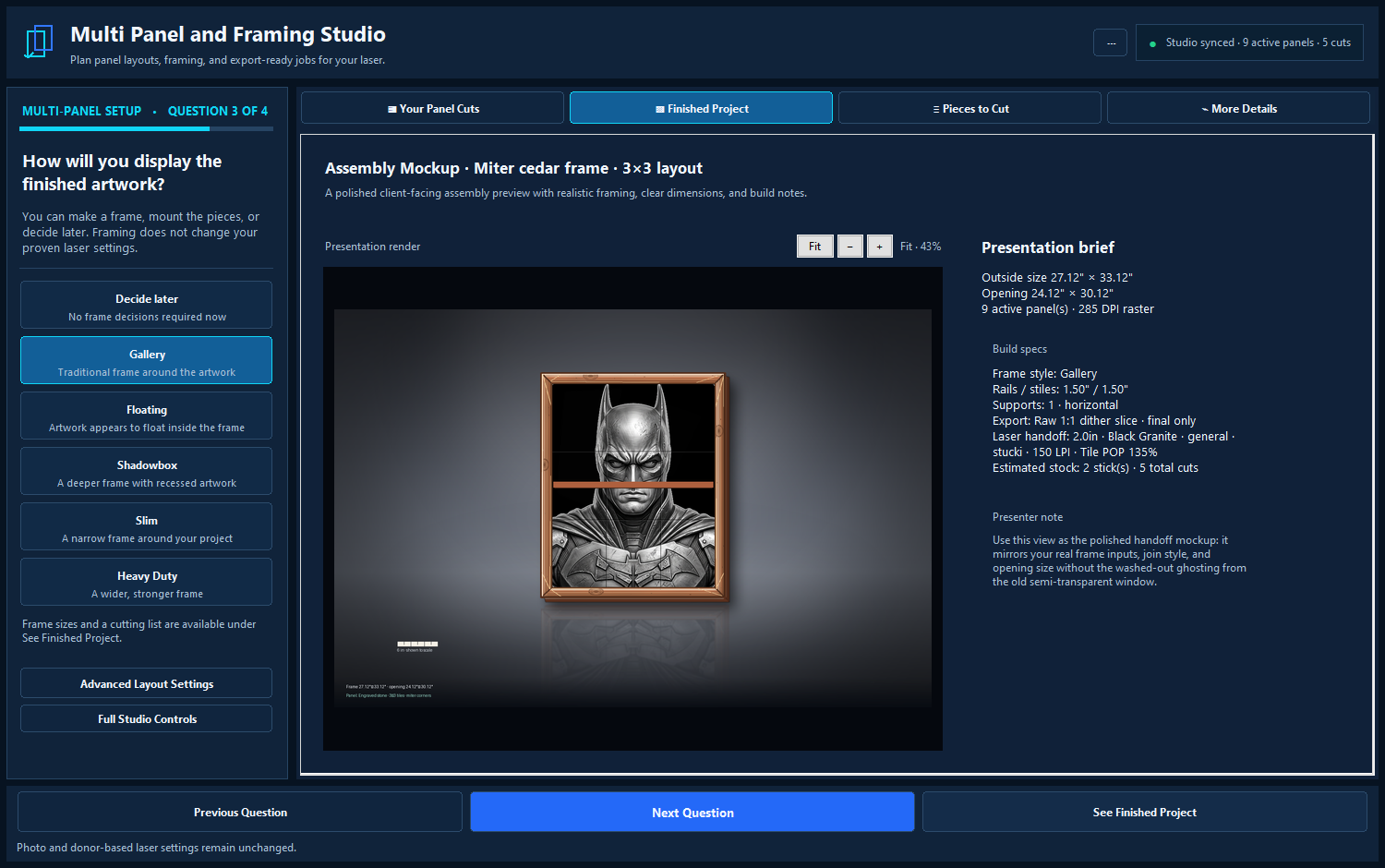
Checkpoint: The opening and outside dimensions are distinct and the intended display style is clear.
STEP 03 / 06
Set the real construction details
Open Full Studio Controls and expand Framing in the Inspector. Review the available stock dimensions, join style, supports and allowance controls. Enter measured stock values rather than trusting a preset to describe the lumber you bought. Review any clearance or fit assumptions before accepting the plan.
Checkpoint: The model describes your real stock and intended construction.
STEP 04 / 06
Read Cut List carefully
Choose Cut List. For a miter plan, the report distinguishes long point outside lengths from short point inside lengths. Top/bottom rails and left/right stiles are separate lines. Read the support pieces too. Do not cut all pieces to a single ambiguous dimension.
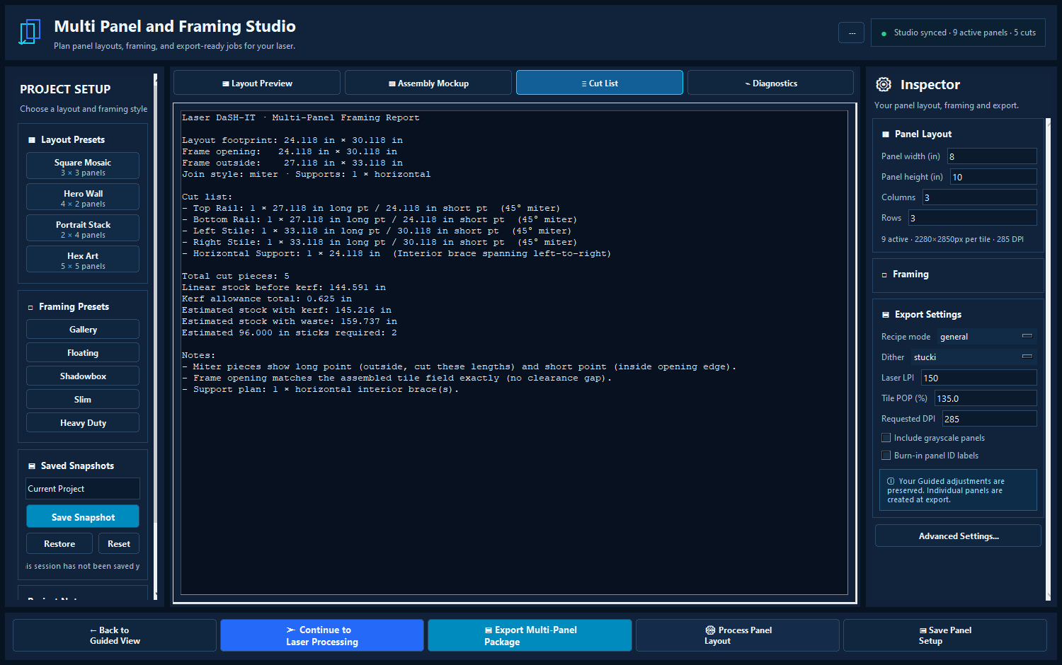
Checkpoint: You can identify the outside and opening dimension for every mitered piece.
STEP 05 / 06
Review kerf, waste and fit
The report lists linear stock, kerf allowance, waste estimate and required stock lengths. These are planning estimates. Check them against your available lengths and saw setup. The pictured report says the frame opening matches the tile field exactly with no clearance gap; account for your real assembly tolerances before cutting.
Checkpoint: You have checked the report’s fit assumption and allowed for the actual cutting process.
STEP 06 / 06
Save the setup and verify before assembly
Use Save Panel Setup or a named snapshot. Keep the cut list with the exported panel package. Re-measure the assembled panel field, confirm the chosen measuring convention on a test cut, and dry-fit the frame before glue or permanent fasteners. Choose mounting hardware appropriate to the actual weight and construction.
Checkpoint: The dry-fit opening, panel field and saved plan agree.